1. Foreword
The development of the IRIS system
- In 1979, Shell Development Company, Westhollow Research Center, Houston, Texas, developed and built an ultrasonic system for inspecting heat exchanger tubes.
- B.I.X. (America), Inc., which later became Pan American Industries, purchased the device from Shell to use and further develop. The name, IRIS (internal rotary inspection system), that they gave to the device is now the generic name for any device that is subject to Shell’s patent.
- Over the years, Pan American has become a specialist in tube inspections. They were aware of the problems and limitations of the original system. Pan American then used its knowledge, which it has gained through its services, for research and development to build a more efficient IRIS system.
- Under Shell’s license, Pan American has developed a more compact version of the IRIS system and increased its inspection capabilities. The current model, Series IV, is a very reliable and user-friendly system.
- In 1997, Pan American Industries developed a digital IRIS system. The new system makes it possible to store all measurements in the computer and visualize the measurement results using a C-scan.
2. Introduction
General
- Heat exchangers and steam boilers contain many tubes, each of which is in turn subject to a certain degree of corrosion.
- The wall thickness, where the tube is thinnest, determines whether it is still suitable for further use. If the wall thickness has decreased to allow the tube to leak or crack due to internal pressure, or if the wall thickness can be predicted to be reduced by the next scheduled inspection, the tube is no longer suitable for production. After all, an unplanned standstill due to the failure of a heat exchanger or steam boiler entails a huge additional cost.
- Although the general loss of wall thickness of the tube refers to the entire damage due to corrosion, this alone is not a reliable factor in determining the condition of the tube. A few small pits where the wall is very thin determine that the tube is unsuitable for further use, even when generally little corrosion is present. To find such pitting and to measure the wall thickness one needs a device that can measure the wall thickness over the entire surface and this with a good resolution.
- IVT Inspections NV, has such a device, namely the IRIS system. After ten years of intensive use, the system has developed into a user-friendly inspection tool, which is now used in many companies.
- The original intention of the system was to measure the wall thickness of air-cooled heat exchanger tubes (airfin tubes). IRIS is currently being used for preventive research in many different types of heat exchangers and steam boilers, in electrical and nuclear power plants, petrochemical and chemical companies, offshore installations, shipping and food industry, etc…
- IRIS uses the conventional pulse echo method to measure the wall thickness, but uses a new method to display the measurement results. All measurements made during one scan of the circumference of the tube are imaged on a computer screen. The image is a stationary rectilinear section of the circumference of the tube.
- This new way of presenting has made it possible to measure the wall thickness of corroded tubes up to a minimum wall thickness of 0.5 mm. IRIS can measure the remaining wall thickness regardless of whether the metal loss is internal or external, whether it is a smooth wall thickness decrease or local pitting.
3. Working principle of the IRIS system
Principle
- The operation of IRIS is based on the ultrasonic pulse-echo technique for measuring wall thicknesses. The essential features of this method are illustrated in Figure 1a.
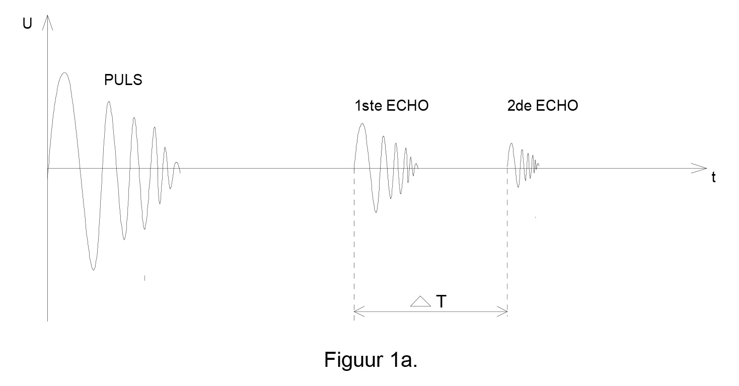
- A converter converts an electrical pulse into an ultrasonic sound vibration. Because the efficiency of the energy transfer between a liquid and a solid is higher than between a gas and a solid, IRIS uses a liquid, namely water, to conduct the waves.
- The ultrasonic pulse passes through the water to the wall of the tube. There, most of the energy from the pulse is reflected back to the converter. A small part, about one-tenth, propagates in the tube wall to the outer wall where the second reflection in turn occurs. A small part of this second reflection, about one-tenth, goes through the tube again through the water to the converter.
- The two echoes follow the same path back as the original pulse. In the converter, they generate electrical pulses, separated by time, to propagate through the entire wall of the tube. Since this time is proportional to the wall thickness, it can be calculated by measuring the time difference between the echoes from the inner wall and the outer wall. This is accomplished electronically.
4. The ultrasonic probe
The probe
- The way in which the pulse-echo method is used to examine heat exchanger and steam boiler tubes is shown in figure 2. The ultrasonic transducer is mounted in the probe, which is centered in a tube.
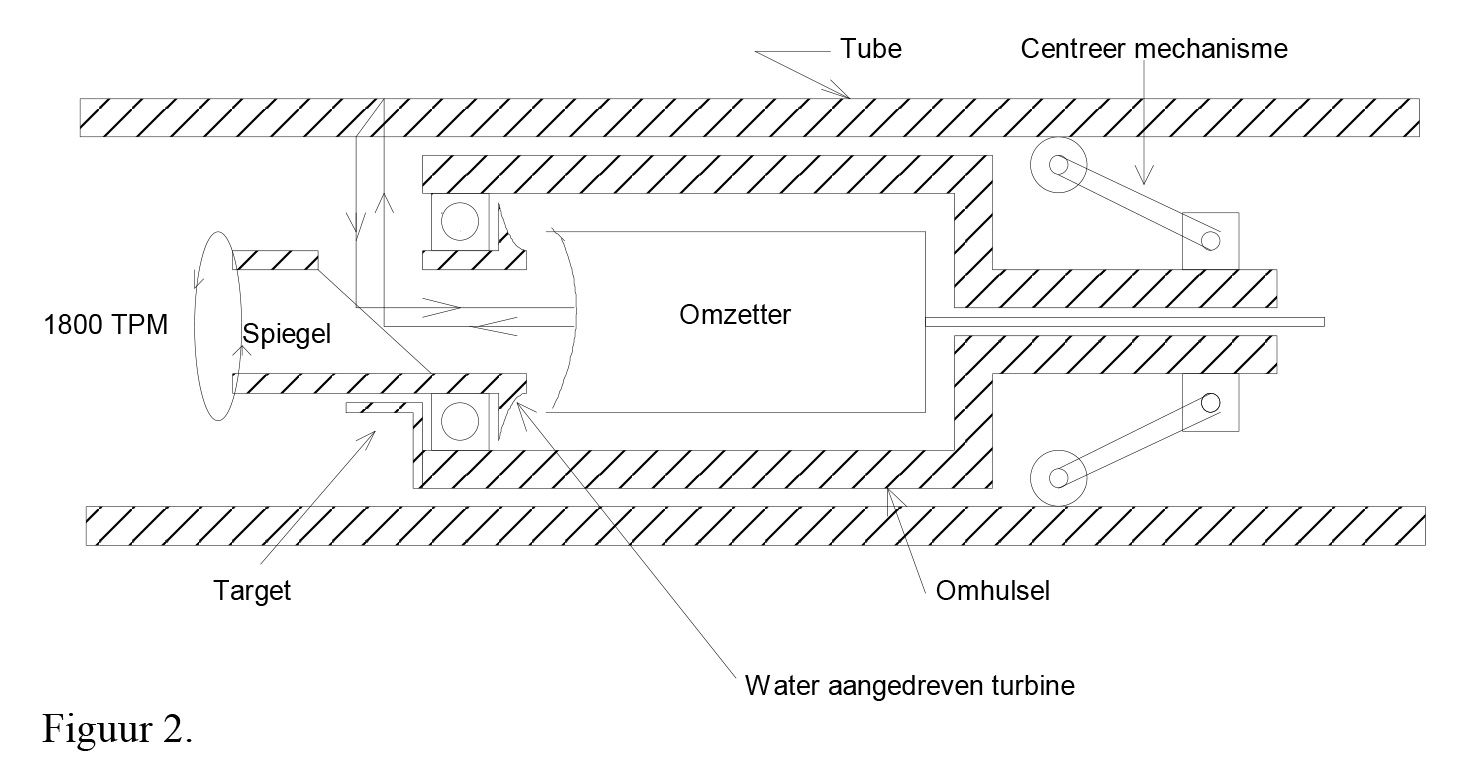
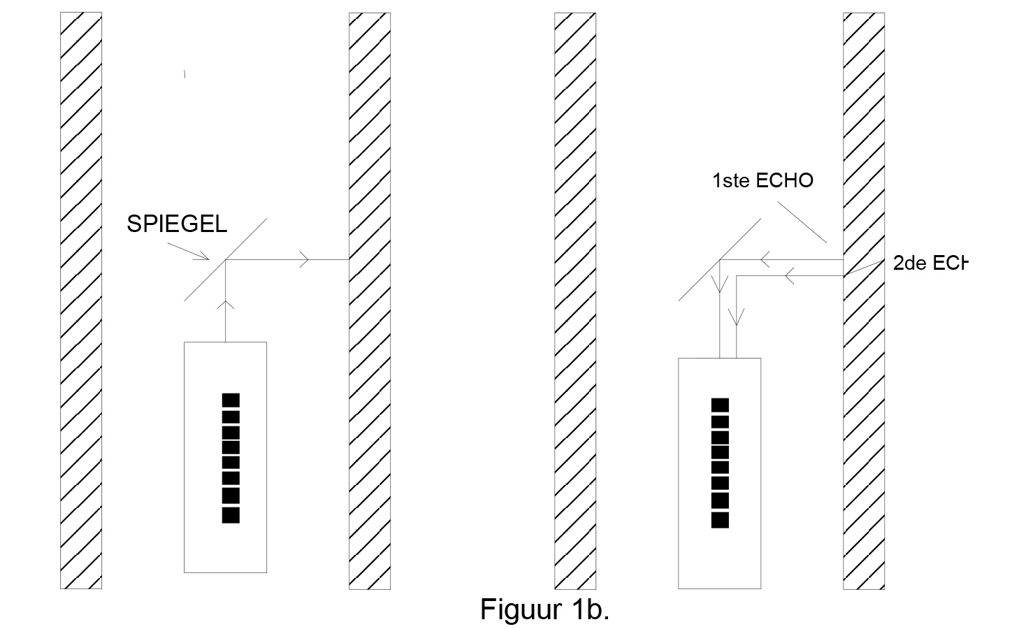
- The ultrasonic pulses are emitted parallel to the axis of the probe. These pulses are reflected on a mirror turned 45 ° so that they are perpendicular to the wall of the tube (Fig. 1b).
- The mirror is mounted on a water-powered turbine rotating on an axis parallel to the probe axis. As the mirror rotates, the successive ultrasonic pulses scan the circumference of the tube wall, so that the entire circumference is scanned during one revolution of the mirror.
- With a pulse repetition rate of 10 kHz and a mirror revolution speed of 1800 rpm, the entire wall is scanned, and no part of the tube wall outline will be missed.
5. The electronic display
Display
- What makes this system so unique is the way in which the pulse-echo wall thickness measurements are visualized.
- The time between the inner and outer wall reflection and the time proportional to the distance between the mirror axis and the tube wall are measured. These measurements are processed electronically. All the measurements taken during one rotation of the mirror are displayed on a computer screen, which shows a stationary, rectilinear image of the cross-section of the wall.
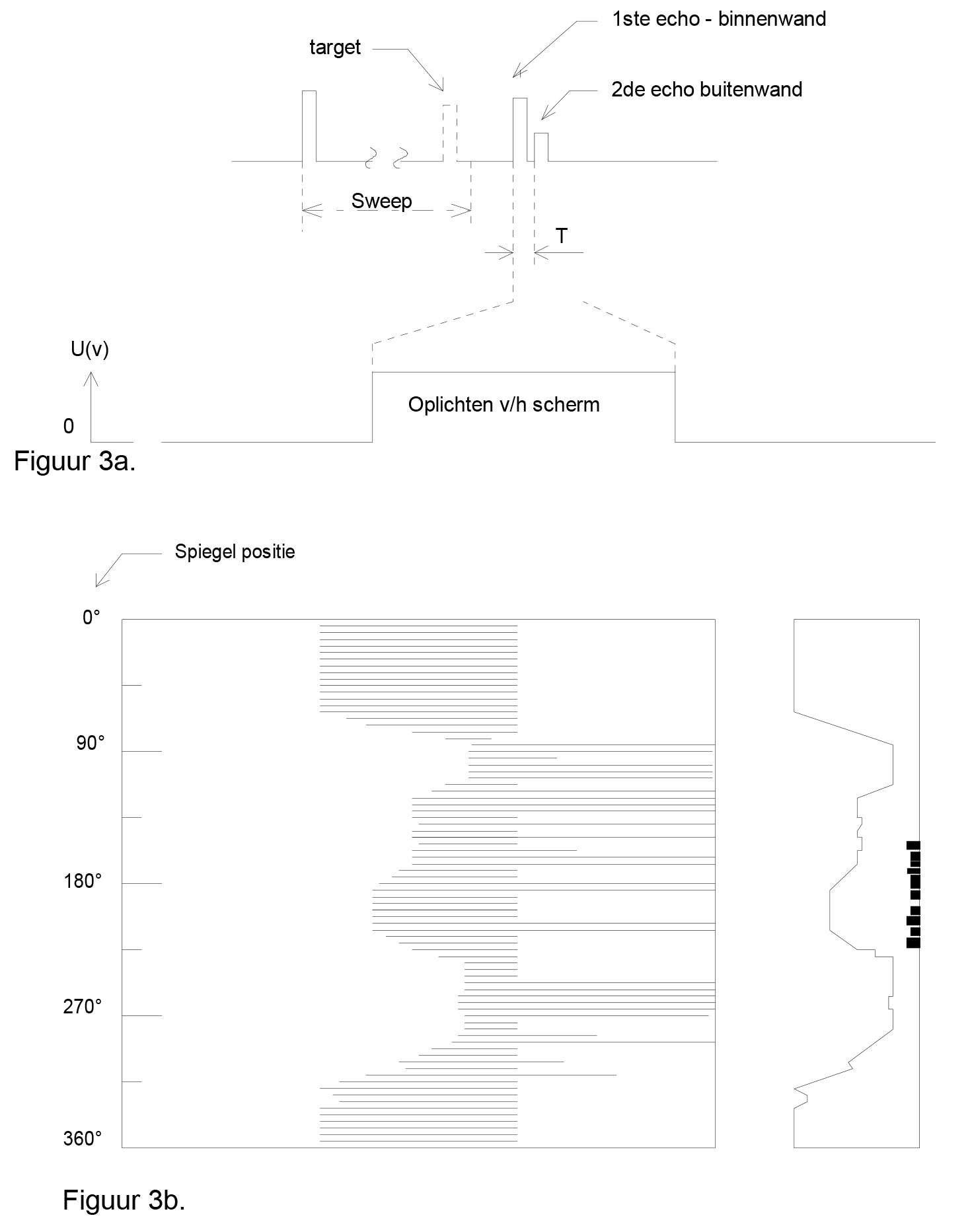
- Figure 3 shows how the image is generated.
- At the top of the figure is shown the time diagram of the emitted pulse and of the echoes reflected by the target (triggering), inner and outer wall.
6. Structure of the image
Interpretation of the image

General operation and principles of the digital IRIS system:
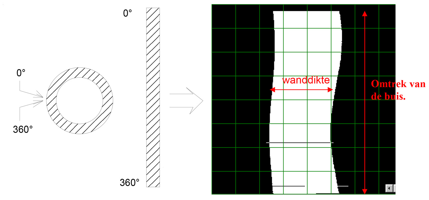
- As suggested above, the height of the image corresponds to the circumference of the tube.
- The width of the white rectangle represents the wall thickness of the pipe.
- The left side is the inner wall of the tube, the right side of the white rectangle is the outer wall of the tube.
7. Examples
General
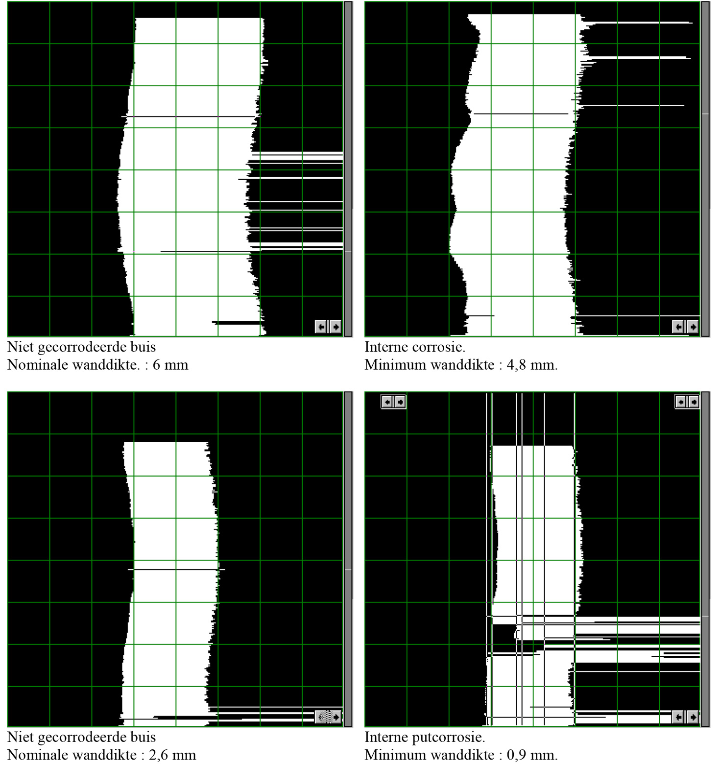
- An uncorroded tube creates a vertical rectangular pattern on the screen of the computer.
- The width of this pattern is equal to a measurement of the wall thickness, and the height of the pattern corresponds to the full circumference of the tube.
Internal defects
- Internal corrosion in a pipe is easily identified as defects on the left side of the rectangular cartridge.
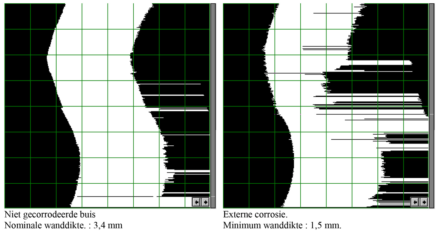
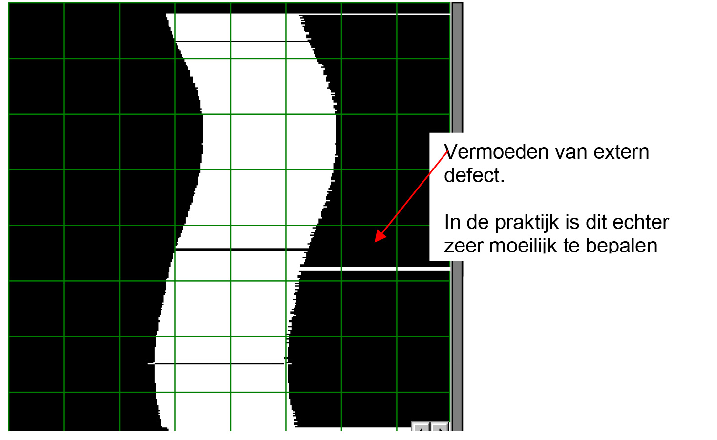
External defects
- External corrosion in a pipe is easily identified as defects on the right side of the rectangular cartridge.
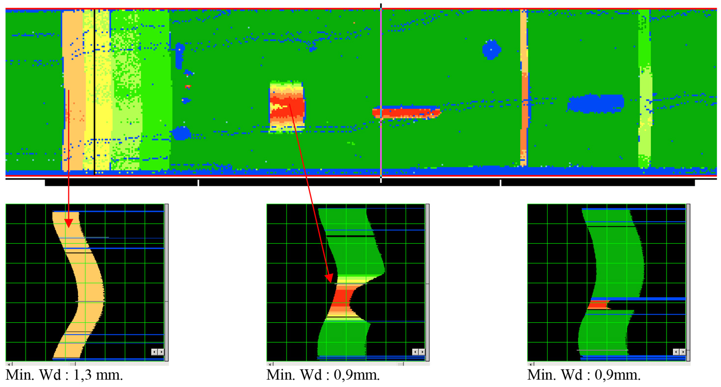
C-scan
- With the new digital IRIS system it is possible to visualize the length of the tube by means of a C-scan.
8. Inspection procedure
- The heat exchanger and boiler tubes MUST be cleaned before they can be inspected. There should be no more chips or other dirt in the tubes. High pressure cleaning is recommended (min. 1000 bar). In exceptional cases, dry cleaning is recommended.
- Before the inspection can be started, all data of the bundle must be known for calibration and reporting. Tube sheet layout, tube dimensions, material of the tubes (speed of sound).
- In a relatively good tube, the pattern on the screen will not change much, and the probe can be pushed at maximum speed. If the tube is severely corroded, the inspection speed must be reduced in order to successfully interpret the ever-changing pattern on the screen.
- The maximum inspection speed is 2.6m per minute if we want to detect corrosion pits with a diameter of 1.5mm. Higher speeds are possible if no pitting is expected.
9. Specifications
- The smallest well we can detect has a diameter of 1.5mm for a tube with an outer diameter of 2.5cm.
Model: Digital IRIS
Power supply: 110 V, 220 V a.c.
Consumption: Max. 120W
Water supply: Min. 3 bar of pure water free from air bubbles
Temperature range: 2 °C to 48 °C
Possible diameters: 9mm ID to 100mm
Center pieces: Size 1: 17mm to 26mm ID, Size 2: 23mm to 43mm ID, Size 3: 34mm to 76mm OD
Probe diameters: Size 1: 12mm OD, Size 2: 17mm OD
Converters: 10MHz, 15MHz
Length of the probes: 15m / 30m
10. Limit detection
General
- There are several factors that determine the detection limit in pipes with diameters larger than 1 ½” (38.1 mm OD) to detect internal or external Ø 1.5 mm wells.
The size of the focus point
- The transducers (ultrasonic transducers) have a focusing distance of 45.72 mm. This means that the focus point size is 1.5mm at a distance of 45.72mm from the transducer.
- For tubes with larger diameters, such as 3” tubes, the focus point is increased by the divergence of the ultrasonic beam. An additional factor is the material thickness. The ultrasonic beam diverges more in the pipe wall than in the water. To determine the focus distance, the following formula applies: “+ 4 x wall thickness”.
- Example: If the wall thickness of the pipe is 3.2 mm, the focus distance will be increased by 12.8 mm.
- Conclusion: As a result, the focus point becomes even larger, i.e. the diameter of the ultrasonic beam increases.
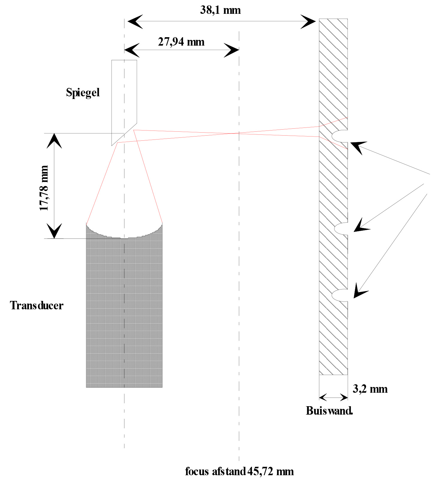
- For this reason, small defects cannot be detected as they are overshadowed by the ultrasound beam.
- Note: The manufacturers of the ultrasonic transducers are limited to make the focus distance greater than 45.72 mm.
- In certain circumstances, the ultrasound may still pick up the edge of the defect see figure below.
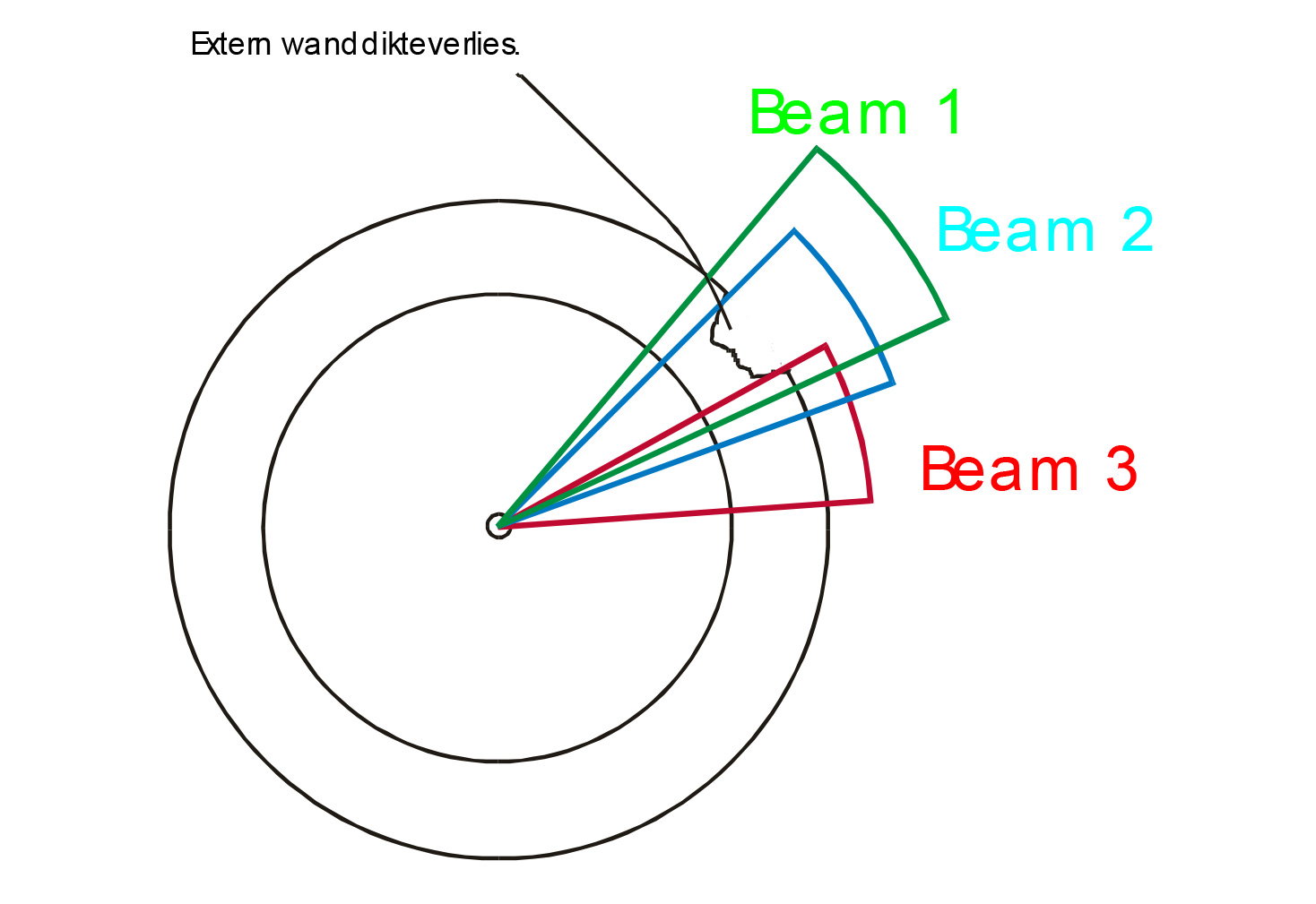
- A) Beam 1: The external wall thickness loss is completely overshadowed by the ultrasonic pulse and is not detected.
- B) Beam 2: The edge of the external well is just detected by the pulse.
- C) Beam 3: The edge of the external well is just detected by the pulse.
- At B) and C) no wall thickness loss can be observed. In some cases one can only refer to a suspicion of external wall thickness loss because in this case a small signal loss occurs.
The height of the display
- Structure of the statue.
- As suggested above, the height of the image corresponds to the circumference of the tube.
- The circumference of a 3” tube is 239.3 mm. The height of the screen on which the IRIS signal is displayed is only 140 mm. Consequently, the resolution is compressed by a factor of 1.7.
- Even if the IRIS system detects small pits, it is still difficult for the inspector to observe these pits in practice, as with smaller pipe diameters.
Want to know more about capabilities of IRIS?